Archive for the ‘Networking’ Category

Here are the basic elements of a network with summarized recommendations from structured cabling specification 568.

7CLDIN24-6-DataSmallBuilding Entrance Requirements
These are the specifications for the point at which the cabling enters a building.  These include the type of surge protecting device and the placement of the cabling used to connect in between wiring.

images

 Equipment Room
This is the existing telecommunications closet. It is the area where communication racks,cables, hardware devices (patch panels, switches, routers, etc.) are located.

It is recommended that the equipment room is located in the middle of the office space. This is to achieve approximately equal length of cables running from the equipment room to work areas and to ensure reliable transmission of data.

1307125224_212399842_1-Pictures-of--Voice-and-Data-Cabling-Fiber-Optics-Cat-5-Cat-6-Fusion-Splicing-Rack-and-StackBackbone Cabling
It is the cabling between floors and equipment rooms (also extended between buildings). It provides the interconnection between equipment room and building entrance site (including cross connects, patch cords, and terminators).

It is recommended to double or triple the length of backbone cable. This provides for possible expansion and redundant connections.

Backbone cable maximum distance limitation:

• Voice grade 100ohm UTP — 800 meter
• STP data grade 150 ohm — 90 meter
• Multimode 62.5/125um fiber — 2000 meter
• Patch cable — 3 to 6 meter

Spending more money for the backbone cabling is recommended and selecting fiber optic over copper wire is the best choice.

IT-Infrastructure1-300x184Horizontal Cabling
It it the cable that runs from the workstation outlet to each terminal in the equipment room. It also includes the cable run from the wall outlet to each workstation, cable in equipment closets that connects network devices.

Horizontal cable maximum distance limitation:

• Between workstation outlet to workstation — 3 meter
• Between  equipment in the telecom closet — 6 meter
• Between telecom closet to workstation outlet — 90 meter

* Cable lengths from end to end should not exceed 100m.

It is recommended that horizontal cabling be rated for cat5 use. When installing horizontal cable, it is important to avoid any sources of EMI.

ComputerRoom_bigWork Area
The are where computers, telephones, patch cables, adapters, etc. are located.
It is recommended to provide a wall jack for each cat5, STP, and FO cable for future expansion.


Source: Structured Cabling System by Nortel Networks

WAN Optimization

Posted: 02/29/2012 in Networking
Tags: ,

WAN Optimization is an important part of network management. It allows the priority of traffic and a guaranteed amount of bandwidth for applications. With WAN Optimization, unwanted traffic can be blocked, schedule inbound and outbound traffic, give priority to certain hosts, and enforce other policies.

WAN Optimization is a collection of techniques for increasing data-transfer efficiencies across wide area networks. The most common measures of TCP data-transfer efficiencies are throughput, bandwidth requirements, latency, protocol optimization and congestion.

Two common Business WAN topologies:
– Branch to Headquarters for email, content management systems, database applications, and Web delivery.
– Data Center to Data Center (DC2DC) include replication, back up, data migration, virtualization, and other Business Continuity/Disaster Recovery BC/DR flows.

WAN Optimization techniques include deduplication, data compression, data prioritization, latency optimization, caching/proxy, forward error correction, protocol spoofing, traffic shaping, equalizing, connection limits, simple rate limits. Sample of Optimization Technology are VPN Tunneling or Virtual Private Network (VPN) and Multiprotocol Label Switching (MPLS).

WAN optimization offers increased network and bandwidth scalability, improved application performance and high availability.  Some Companies implementing WAN Optimization are Bluecoat, Cisco, Citrix, Juniper.

User environment management (also abbreviated to UEM) is a computing term used to describe the management of a user’s experience within their desktop environment.

triCerat’s user workspace management and desktop management solutions protect thousands of IT organizations worldwide from the operational and security risks that can severely impact their desktop and application delivery infrastructure.

triCerat has been a pioneer in printing and user management solutions for Windows System Administrators.

Source:
http://en.wikipedia.org/wiki/User_environment_management
http://www.tricerat.com/

Fiber Optic Pigtails

Posted: 01/17/2012 in Cabling
Tags: , , ,
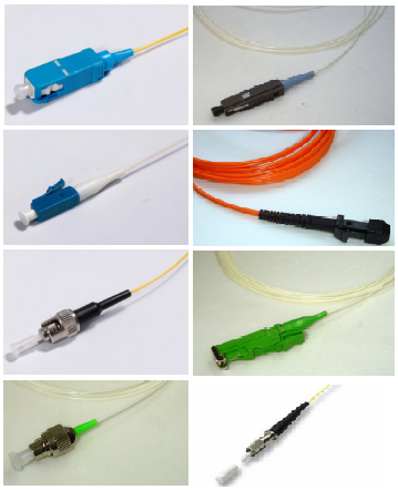
FO Pigtail Termination

FO pigtail termination from left to right: SC, LC, ST, FC, MU, MTRJ, E200, DIN

Fiber Optic pigtail is a piece of fiber optic cable terminated at one end with a fiber optic connector.
FO pigtails are used to link the fiber optic cable with a fiber optic equipment, the connector at one end is used to link the equipment, while the other end is melted together with a fiber cable.

The most common types of FO pigtails have a fiber cable diameter of .9mm

Fiber optic pigtail Specifications (example):
Types: single mode, multimode
Terminations: FC, SC, ST, MU, LC, D4, DIN, E2000, MT-RJ, MPO, SMA, E2000, FDDI, and ESCON
Insertion Loss (dB): less than 0.2 (PC and UPC)
Exchangeability: less than 0.2 dB
Tensile Strength: less than 0.2 dB (0 to15 kgf)
Temp. Range: (- 40 to +80 degree centigrade)

Image

What's inside a Network Socket?

Back to Basic!

We usually look for a Network Socket every time we need a “wired” Internet Connection (most are familiar with the name Internet Socket).

Network Sockets is the end point in a communication across a network, that’s what Wikipedia says.

I use to wire twisted pair cables, the EIA/TIA 568A or B Standard (the WoOWbBWgGWbrBr stuff!) but never I had experience wiring an Ethernet socket. How would the crimped cable work if there’s no network socket installed? Unless cables are directly connected to routers and switches! I saw this easy to follow instruction on ‘How to Wire an Ethernet Socket’. http://www.handymanhowto.com/2009/01/19/how-to-install-an-ethernet-jack-for-a-home-network/. The order of wires is basically  the same but the method of wiring them is different. It is really not an easy or should I mean a fast-to-do job, specially the cabling part. The technicians within my team usually do this network socket stuff. Well, If in case you want to wire a personal network socket, check the link and I hope it helps. 😉

EIGRP (a Cisco proprietary routing protocol) is a classless, enhanced distance-vector protocol that uses the concept of Autonomous System to describe the set of contiguous routers that run the same routing protocol and share routing information. EIGRP is a routing protocol that includes the subnet mask in its route updates. EIGRP is suitable for very large networks. It has a maximum hop count of 255.

EIGRP stores data in three tables: Neighbor Table, Topology Table, and Routing Table.

Successor and Feasible Successor
A Successor is the next hop router that provides the least distance to a destination AND is guaranteed not to be a part of some routing loop. A Feasible Successor is the next hop router that is guaranteed not to be a part of some routing loop.

Configuration

1. Configure each of the router’s interfaces.

2. Configure EIGRP as the network’s routing protocol.

R1(config)#router eigrp 10
R1(config-router)#network 192.168.100.0
R1(config-router)#network 192.168.10.0

R2(config)#router eigrp 10
R2(config-router)#network 192.168.100.0
R2(config-router)#network 192.168.200.0
R2(config-router)#network 192.168.20.0

R3(config)#router eigrp 10
R3(config-router)#network 192.168.200.0
R3(config-router)#network 192.168.30.0

3. Optional. Use passive-interface command to prohibit interface/s from sending or receiving Hello Packets. The interface will not send or receive route information.

R3(config)#router eigrp 10
R3(config-router)#passive-interface serial 0/0

4. Use the no-auto summary command to disable summarization. EIGRP will advertise all subnets between two routers. Manual summarization may be used for lager networks.

R1(config)#int f0/0
R1(config-if)# ip summary-address eigrp 10 192.168.10.0 255.255.255.0

R1(config)#router eigrp 10
R1(config-router)#no auto-summary

5. Verify configuration.
Use the following commands to check.
show ip route will show the entire routing table.
show ip route eigrp will show only eigrp entries in the routing table.
show ip eigrp neighbors will show all eigrp neighbors.
show ip eigrp topology will show entries in the eigrp topology table.

R3#show ip route
C    192.168.30.0/24 is directly connected, FastEthernet0/0
D    192.168.10.0/24 [90/2684416] via 192.168.200.1, 00:01:09, Serial0/0
C    192.168.200.0/24 is directly connected, Serial0/0
D    192.168.20.0/24 [90/2172416] via 192.168.200.1, 00:01:09, Serial0/0
D    192.168.100.0/24 [90/2681856] via 192.168.200.1, 00:01:09, Serial0/0

R3#show ip route eigrp
D    192.168.10.0/24 [90/2684416] via 192.168.200.1, 00:01:09, Serial0/0
D    192.168.20.0/24 [90/2172416] via 192.168.200.1, 00:01:09, Serial0/0
D    192.168.100.0/24 [90/2681856] via 192.168.200.1, 00:01:09, Serial0/0

R2#show ip eigrp neighbors
IP-EIGRP neighbors for process 10
H   Address                 Interface       Hold Uptime   SRTT   RTO  Q  Seq
                                            (sec)         (ms)       Cnt Num
1   192.168.200.2           Se0/1             13 00:05:20   32   200  0  2
0   192.168.100.1           Se0/0             13 00:09:04  660  3960  0  4


R1#show ip eigrp topology

IP-EIGRP Topology Table for AS(10)/ID(192.168.100.1)

Codes: P - Passive, A - Active, U - Update, Q - Query, R - Reply,
       r - reply Status, s - sia Status

P 192.168.100.0/24, 1 successors, FD is 2169856
        via Connected, Serial0/0
P 192.168.10.0/24, 1 successors, FD is 28160
        via Connected, FastEthernet0/0
P 192.168.30.0/24, 1 successors, FD is 2684416
        via 192.168.100.2 (2684416/2172416), Serial0/0
P 192.168.20.0/24, 1 successors, FD is 2172416
        via 192.168.100.2 (2172416/28160), Serial0/0
P 192.168.200.0/24, 1 successors, FD is 2681856
        via 192.168.100.2 (2681856/2169856), Serial0/0

RIP, a distance-vector routing protocol, works well in small networks. It sends the complete routing table to all active interfaces every 30 seconds. RIP uses hop count as its routing metric to determine the best path to in a network and has a maximum hop count of 15. It has an Administrative Distance of 20 while Static Routes has an AD of 1.

Three versions of RIP are:
RIPv1 uses classful routing, lacks support for Variable Length Subnet Masks (VLSM).
RIPv2 uses classless routing, supports Classless Inter-Domain Routing (CIDR).
RIPng an extension of RIPv2 for support of IPv6.


Configuration

1. Configure each of the router’s interfaces.

2. Configure RIP as the network’s routing protocol and add all network to be advertised.

R1(config)#router rip
R1(config-router)#network 192.168.10.0
R1(config-router)#network 192.168.10.100


R2(config)#router rip
R2(config-router)#network 192.168.100.0
R2(config-router)#network 192.168.200.0
R2(config-router)#network 192.168.20.0


R3(config)#router rip
R3(config-router)#net 192.168.200.0
R3(config-router)#net 192.168.30.0

3. Use passive-interface command to prevent RIP update broadcsts from being sent out a defined interface. The same interface can still receive RIP updates. (optional)

R1(config)#router rip
R3(config-router)#passive-interface serial 0/0

4. verify connection and routing configuration.

Ping Samples:

R1#ping 192.168.30.1
Type escape sequence to abort.
Sending 5, 100-byte ICMP Echos to 192.168.30.1, timeout is 2 seconds:
!!!!!
Success rate is 100 percent (5/5), round-trip min/avg/max = 4/64/100 ms


R2#ping 192.168.10.1
Type escape sequence to abort.
Sending 5, 100-byte ICMP Echos to 192.168.10.1, timeout is 2 seconds:
!!!!!
Success rate is 100 percent (5/5), round-trip min/avg/max = 1/16/36 ms

R2#ping 192.168.30.1
Type escape sequence to abort.
Sending 5, 100-byte ICMP Echos to 192.168.30.1, timeout is 2 seconds:
!!!!!
Success rate is 100 percent (5/5), round-trip min/avg/max = 32/43/64 ms


R3#ping 192.168.10.1
Type escape sequence to abort.
Sending 5, 100-byte ICMP Echos to 192.168.10.1, timeout is 2 seconds:
!!!!!
Success rate is 100 percent (5/5), round-trip min/avg/max = 60/64/68 ms

Routes:


R1#sh ip route
R    192.168.30.0/24 [120/1] via 192.168.100.2, 00:00:23, Serial0/0
C    192.168.10.0/24 is directly connected, FastEthernet0/0
R    192.168.200.0/24 [120/1] via 192.168.100.2, 00:00:23, Serial0/0
R    192.168.20.0/24 [120/1] via 192.168.100.2, 00:00:23, Serial0/0
C    192.168.100.0/24 is directly connected, Serial0/0


R2#sh ip route
R    192.168.30.0/24 [120/1] via 192.168.200.2, 00:00:23, Serial0/1
R    192.168.10.0/24 [120/1] via 192.168.100.1, 00:00:21, Serial0/0
C    192.168.200.0/24 is directly connected, Serial0/1
C    192.168.20.0/24 is directly connected, FastEthernet0/0
C    192.168.100.0/24 is directly connected, Serial0/0


R3#sh ip route
C    192.168.30.0/24 is directly connected, FastEthernet0/0
R    192.168.10.0/24 [120/1] via 192.168.200.1, 00:00:10, Serial0/0
C    192.168.200.0/24 is directly connected, Serial0/0
R    192.168.20.0/24 [120/1] via 192.168.200.1, 00:00:10, Serial0/0
R    192.168.100.0/24 [120/1] via 192.168.200.1, 00:00:10, Serial0/0

Do you experience wireless network connection problems from home? I saw a great step by step diagram that may help ypu solve your problem. You can troubleshoot wireless network connection issues by yourself with the help of this flow chart.

In case you do not have that technical person around, you could probably make your wireless connection work! 🙂

Default Routing

Posted: 08/24/2011 in Networking

Default Route is known as the gateway of last resort. If a route is not known, packets are forwarded to a default-route of a router which generally leads to another router. Default routes are used on stub networks – those with only one exit path out of the network.

To create a default route, use the following syntax:
ip route 0.0.0.0 0.0.0.0 next-hop_address
or
ip route 0.0.0.0 0.0.0.0 exit_interface
or
ip default-network network_address

The three syntax differ in such a way that:
– if the next hop address is used, AD is set to 1.
– if the exit interface is used, AD is set to 0.
– if ip default-network is used, the default network will be advertised of igp is configured on th router.

Suppose we want to send all unknown routes outside our network. Let’s say our network is 10.0.0.0.

Here’s how to configure a default route given the topology above.

1. Configure each of the router’s interfaces.

2. Configure Default Routing.

R2(config)#ip route 0.0.0.0 0.0.0.0 10.10.10.1

R3(config)#ip route 0.0.0.0 0.0.0.0 200.200.200.1

3. use ip classless command for subnetted networks

R2(config)#ip classless

R3(config)#ip classless

4. Verify the configuration

R2#ping 200.200.200.2
Type escape sequence to abort.
Sending 5, 100-byte ICMP Echos to 200.200.200.2, timeout is 2 seconds:
!!!!!
Success rate is 100 percent (5/5), round-trip min/avg/max = 48/61/72 ms

R3#ping 10.10.10.2
Type escape sequence to abort.
Sending 5, 100-byte ICMP Echos to 10.10.10.2, timeout is 2 seconds:
!!!!!
Success rate is 100 percent (5/5), round-trip min/avg/max = 28/54/80 ms

R1#show ip route
Gateway of last resort is not set
C    200.200.200.0/24 is directly connected, Serial0/1
     10.0.0.0/24 is subnetted, 1 subnets
C       10.10.10.0 is directly connected, Serial0/0

R2#show ip route
Gateway of last resort is 10.10.10.1 to network 0.0.0.0
     10.0.0.0/24 is subnetted, 1 subnets
C       10.10.10.0 is directly connected, Serial0/0
S*   0.0.0.0/0 [1/0] via 10.10.10.1

R3#show ip route
Gateway of last resort is 200.200.200.1 to network 0.0.0.0
C    200.200.200.0/24 is directly connected, Serial0/0
S*   0.0.0.0/0 [1/0] via 200.200.200.1

Static routing is a data communication concept describing one way of configuring path selection of routers in computer networks [Wikipedia]. Static Routing is achieved by manually adding routes in each router’s routing table. It is commonly used by Network Administrators preferably on small-scale networks.

To create a static route, use the following syntax:
ip route destination_network network_mask next-hop_address_or_exit_interface [administrative_distance] [permanent]

Here’s a quick tutorial on how to manually add routes to a router’s routing table. Let’s say, we want to connect two different networks through static routing: network 10.10.10.0 and network 10.10.20.0.

1. Configure each of the router’s interfaces.

R1(config)#int s0/0
R1(config-if)#ip add 10.10.10.1 255.255.255.0
R1(config-if)#no sh

R2(config)#int s0/0
R2(config-if)#ip add 10.10.10.2 255.255.255.0
R2(config-if)#no sh
R2(config-if)#clock rate 56000
R2(config)#int s0/1
R2(config-if)#ip add 10.10.20.1 255.255.255.0
R2(config-if)#no sh

R3(config)#int s0/0
R3(config-if)#ip add 10.10.20.2 255.255.255.0
R3(config-if)#no sh
R3(config-if)#clock rate 56000

2. Configure static routing on each router.

R1(config)#ip route 10.10.20.0 255.255.255.0 10.10.10.2
R3(config)#ip route 10.10.10.0 255.255.255.0 10.10.20.1

No static routing configuration is needed on R2 since it is connected in both networks.

3. Verify the configuration

R1#ping 10.10.20.2
Type escape sequence to abort.
Sending 5, 100-byte ICMP Echos to 10.10.20.2, timeout is 2 seconds:
!!!!!
Success rate is 100 percent (5/5), round-trip min/avg/max = 64/65/68 ms

R3#ping 10.10.10.1
Type escape sequence to abort.
Sending 5, 100-byte ICMP Echos to 10.10.10.1, timeout is 2 seconds:
!!!!!
Success rate is 100 percent (5/5), round-trip min/avg/max = 24/56/64 ms

R1#show ip route
     10.0.0.0/24 is subnetted, 2 subnets
C       10.10.10.0 is directly connected, Serial0/0
S       10.10.20.0 [1/0] via 10.10.10.2

R3#show ip route
     10.0.0.0/24 is subnetted, 2 subnets
S       10.10.10.0 [1/0] via 10.10.20.1
C       10.10.20.0 is directly connected, Serial0/0